Choosing a bill validator
The most important thing for a bill validator in a FAST Pinball modern machine is to pick one that runs on 12 volts. There are multiple standards for validators, including 12, 24, and 48 VDC, as well as line voltage 120-240VAC. Obviously a validator that runs on something other than 12V means you need to find a way to get that voltage into your cabinet and it will probably be a pain. So get a 12V validator.
The other thing to look for is one with a "pulse" interface. (There are lots of ways the validator interfaces with the gaming machine, including digital standards, RS-232, etc.) The pulse interface is just a simple switch closure that happens when a bill is inserted and accepted. You configure the specific timing via the validator itself, e.g. if you insert a dollar, it pulses once, if you insert a $5 bill, it pulses 5 times. Or maybe you insert a dollar and it pulses 4 times and a $5 bill pulses 20 times, etc. The specifics don't really matter, since you just configure your game software to know the value of each pulse.
The specific validator we tested and used during the development of this board was the ICT V636-FOM-USD4-T2, available for about $250 from SuzoHapp and other distributors. But again, any validator that runs on 12V and has a pulse interface should be fine.
The following diagram shows the important pins on the validator that we care about. (Again, you'll need to either build an adapter, or cut off the connector it came with and wire in your own 0.100" header with the correct pin locations for the Cabinet I/O board.)
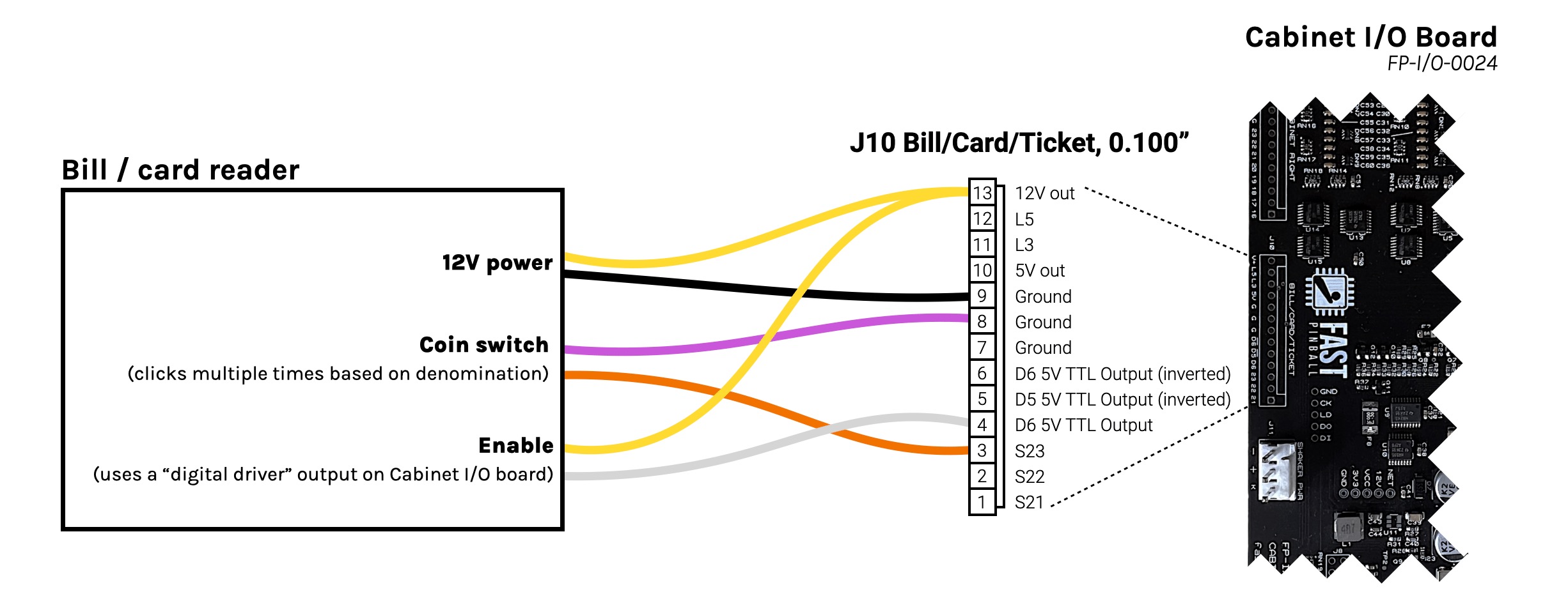
You'll want to use header J10 labeled BILL/CARD/TICKET on the Cabinet I/O board.
12V Power
The bill acceptor needs 12V to operate, which can be provided via J10 Pin 13. (This 12V power is protected and sized for the 4A required by the acceptor.) For the ground, use the ground from Pin 9.
Why Pin 9? Even though the 12V for the bill acceptor low current, it's more current than the switch circuits, so we like to use the ground that is physically closest to the 12V power. That minimizes the small voltage fluctuations exposed to the switches since it's a shorter distance to the 12V power. (Similar in concept to the conversations about the 48V toxic ground, but smaller and localized to this board.)
Pulse output (coin switch trigger)
The validator will send pulses to simulate switch closures associated with adding money to the machine. The exact name of this might vary depending on the model you're using. The one we tested called it CREDIT RELAY (N.O.) and CREDIT RELAY (COMMON)
You'll wire that up just like any switch, using a purple wire to Pin 7, 8, or 9 G, and an orange wire to one of the switch inputs on Pins 1-3. Most likely the "negative" or "common" will be your purple wire, and the "positive" or "normally open" will be your orange wire. But who knows how accurate the labeling is or if it even matters. Just try it, and if it doesn't work, swap the two wires.
Bill validator enable/inhibit
Most bill validators have some sort of input signal used to control whether or not they accept bills. This is used to prevent someone from putting money in a machine when the machine is broken or not fully booted up.
On the validator we tested with, these connections were labeled INHIBIT + and INHIBIT -.
You can read the documentation for your specific validator to understand how this enable signal should be wired. In our example, the enable is an opto isolated input which we can trigger with the TTL logic level digital driver output using Pin 4 D6 as the actual enable signal. If your validator enable is reversed, where it needs the signal to be active high to inhibit, then you can use Pin 6 D6 with the line over it which means "D6 NOT" (inverted) instead.
Connect the other side of the enable input to either Pin 13 V+ or Pin 10 5V depending on the voltage required by your validator. (The one we tested seemed to work with either.)
Then, sending a signal to enable that driver will enable (or not inhibit) the bill acceptor. On our test acceptor, enabling it caused little arrows to start flashing green on the front and it would accept bills. Disabling that driver (or disconnecting it) caused the LEDs on the front to turn off, and it would no longer accept bills.
There might be some other features in the validator, such as status pulses or other control lines. There are plenty of other outputs and inputs on this header if want to use them for various features of your validator.
If you need more infos or you have a report for us feel free to send us a ticket.
Andrea DM
Customer Support Guru
Was this article helpful?
That’s Great!
Thank you for your feedback
Sorry! We couldn't be helpful
Thank you for your feedback
Feedback sent
We appreciate your effort and will try to fix the article